- Preclinical
Wireless implant for freely moving mice
A fully implantable, wirelessly recharged neuromodulator that records and stimulates in freely moving mice.
The problem
Mice are the most widely used animal in medical research, yet bioelectronic medicine studies in mice have been mostly acute, for lack of tools for chronic stimulation and sensing. The size, weight and power needs of such systems either rule mice out or constrain how experiments are designed.
Our approach
A closed-loop implant of about 1.5 cm³, built from off-the-shelf components, recharged by a resonant coil around the animal's home cage and run from our FIMR Studio software over a 2.4 GHz link.
From tethered, acute studies to a fully implantable system
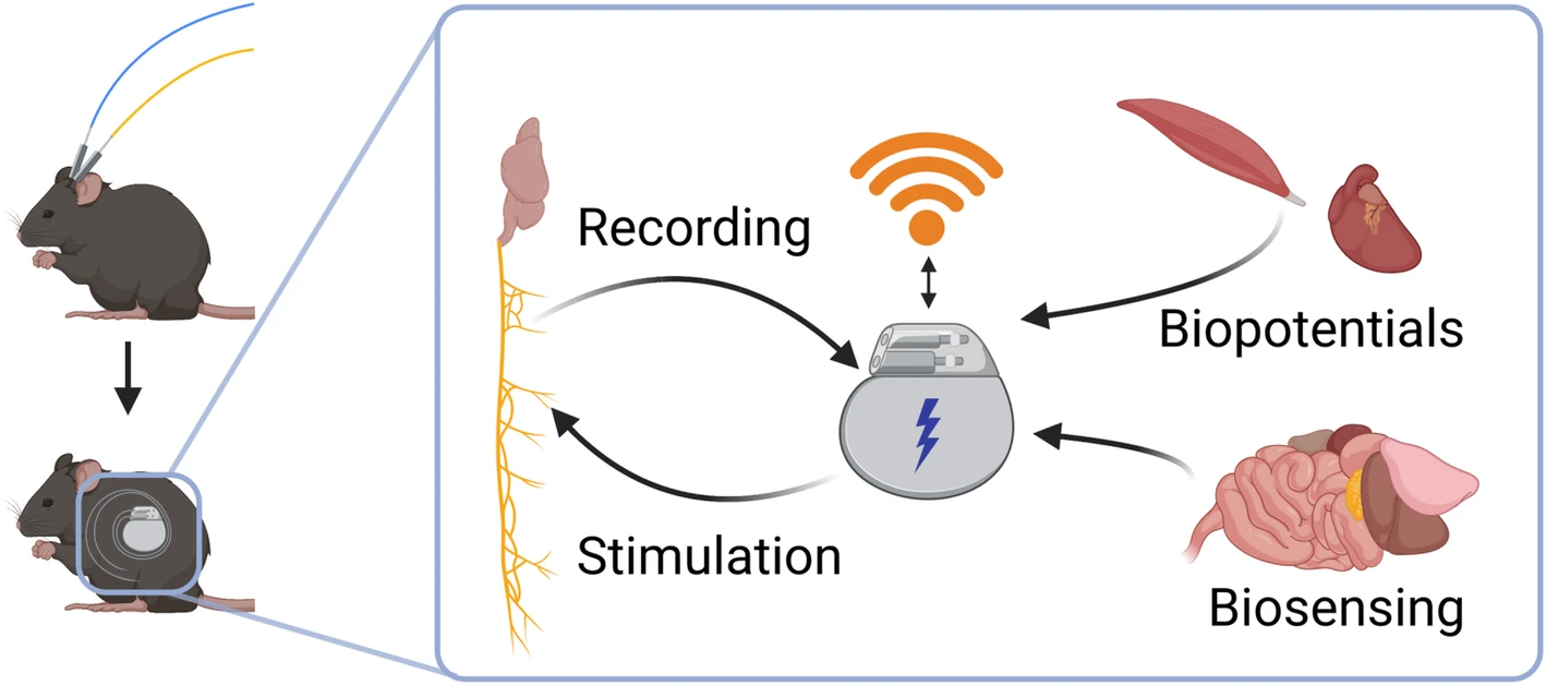
A wireless platform small enough to implant in a mouse can record nerve activity, biopotentials and biosensor signals, stimulate, and exchange data and commands over a wireless link. Experiments can then run chronically in awake, freely moving animals instead of in short tethered sessions.
Our first fully implantable system stimulated the vagus nerve in mice
The system we published in 2022 measured 2.2 cm³ and weighed 2.8 g. Its bidirectional wireless interface read out several physiological signals at once and gave complete control over stimulation, and its wirelessly recharged battery lasted up to five days per charge.
Implanted for vagus nerve stimulation in 12 mice, it provided a functional nerve interface that could induce acute bradycardia. It used only commercially available components and 3D-printed packaging, so that other labs can build it.

The newest implant records, stimulates and recharges in about 1.5 cm³
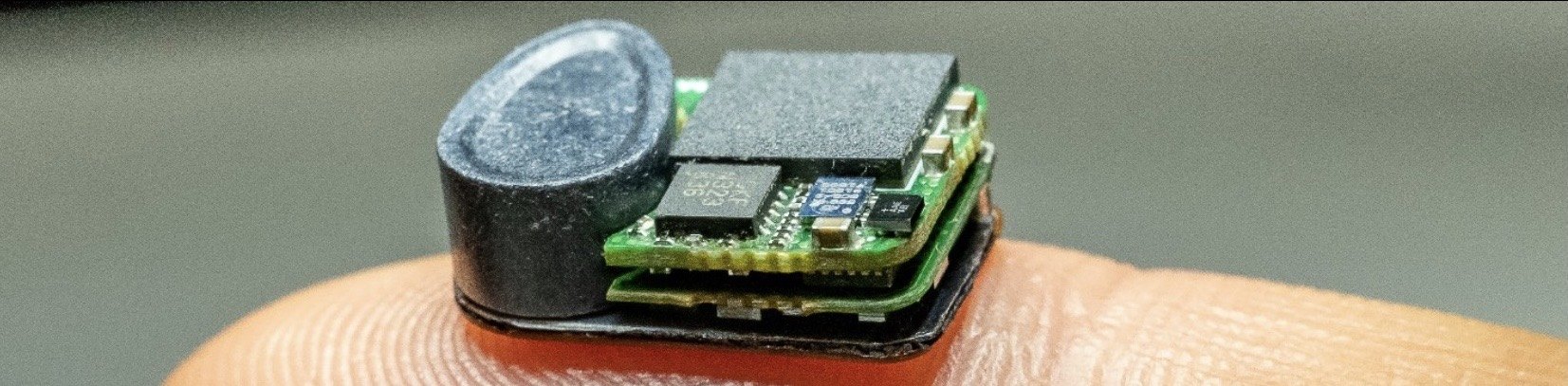
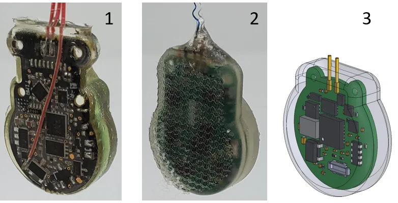
The newest implant is a smaller version of our 2022 system, again built only from readily available parts. Two circuit boards, a ferrite sheet and a charging coil are stacked with an 18.5 mAh lithium polymer battery inside a polymer shell, and a feedthrough carries leads out to nerve cuffs and other electrodes. The radio is a 6.2 × 7 mm module with a built-in antenna.
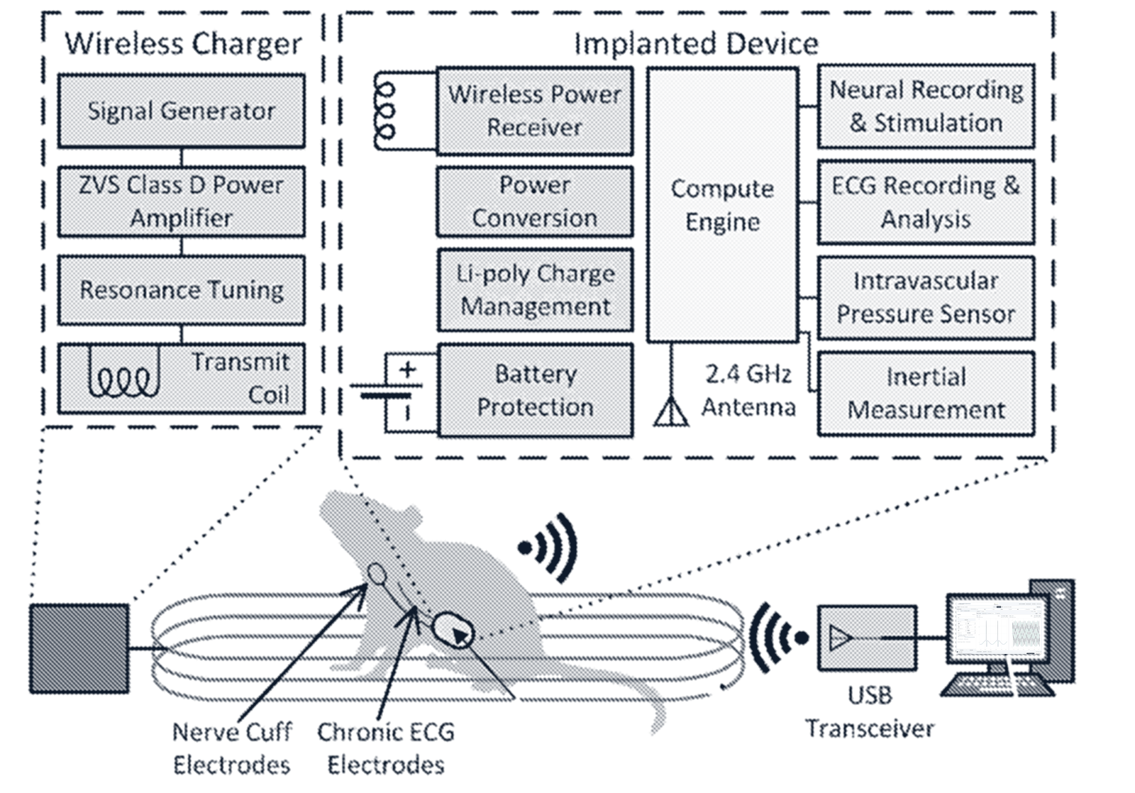
One channel records, one stimulates, and a third can do either. Stimulation supports arbitrary waveforms up to 10 kHz, and the implant computes derived values such as heart rate and runs closed-loop control on board. Our patent application also describes reading ECG, intravascular pressure and motion.
A coil around the home cage keeps it charged
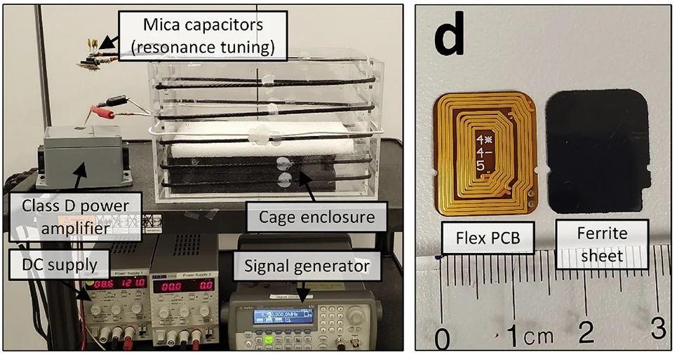
A magnetic resonance charging system surrounds the animal's home cage and transfers power to a receiver in the implant, so chronic studies run without tethers or repeated handling. Data travel the other way, over a 2.4 GHz link to a USB dongle on the host computer.
In the 2022 system, a class D amplifier drove coils wound around the cage, tuned with mica capacitors, and the implant picked up power through a flexible printed coil backed by a ferrite sheet.
Experiments run from FIMR Studio, our control software
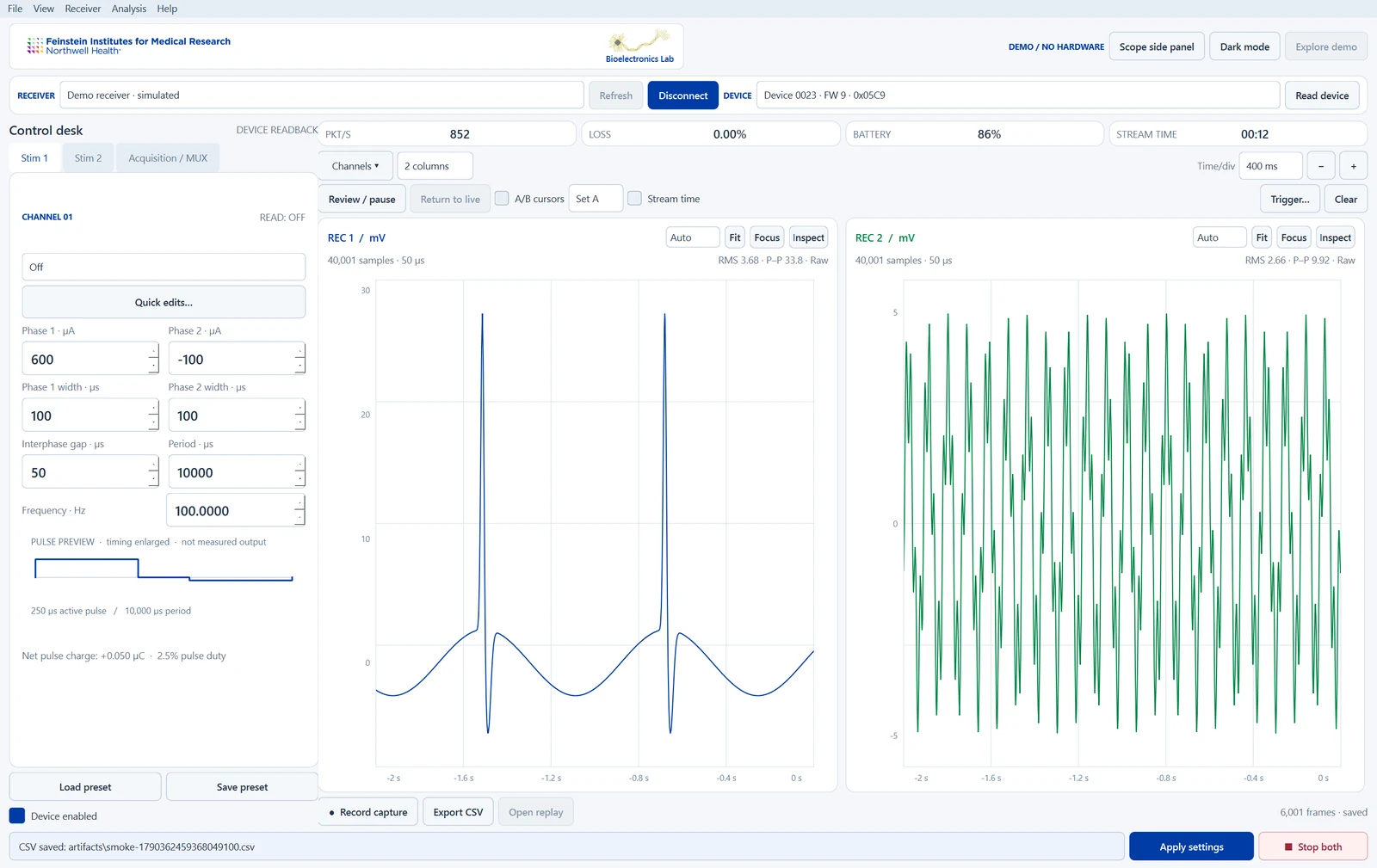
The implant is controlled wirelessly from a USB dongle. FIMR Studio sets up the implant's two independent stimulation channels, choosing pulse amplitudes, widths, the gap between phases and the pulse rate, from a few hertz to 10 kHz, and confirms every change by reading the configuration back from the implant.
Two recording channels stream live alongside the implant's battery, motion, temperature and humidity readings. Researchers can pause and scroll back through the stream, measure between cursors, trigger on and average repeated responses, and record raw data to a file for later replay and export.
Closed-loop control can run on board the implant or with the computer in the loop, where a radio round trip between the implant and the computer takes less than 1 ms.
A compact stimulation app
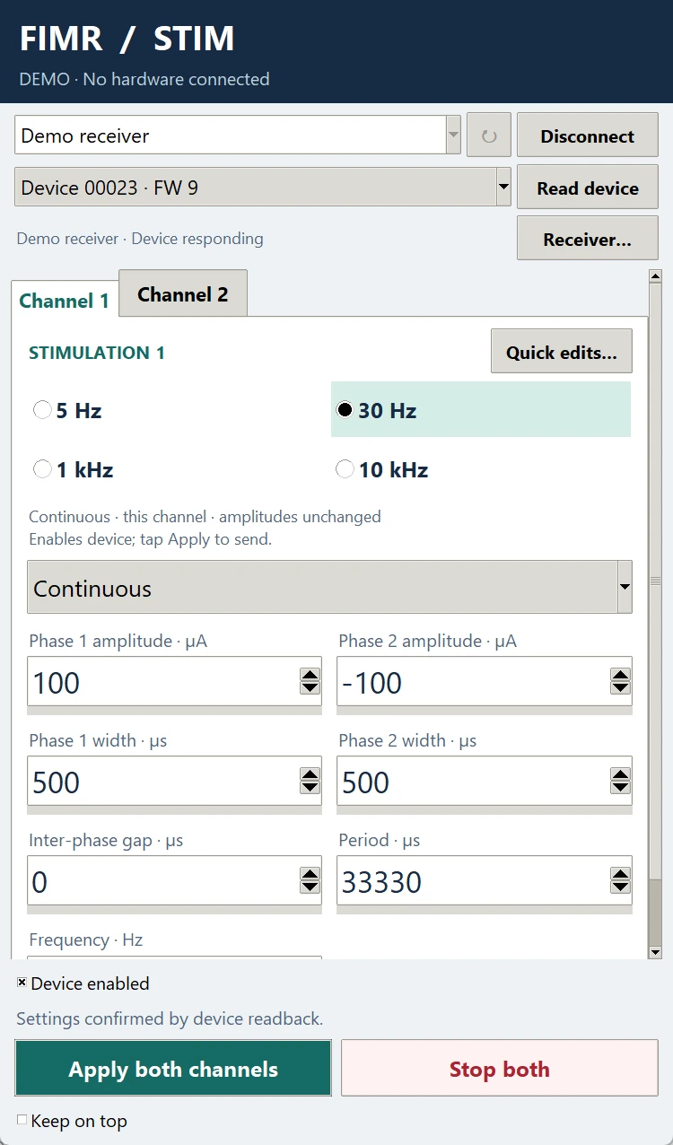
For stimulation-only sessions, FIMR Stim is a compact companion app. On a computer it is designed to sit beside an oscilloscope on the same screen. Each channel has one-tap frequency presets of 5 Hz, 30 Hz, 1 kHz and 10 kHz, and the app applies both channels together, reporting success only after reading the settings back from the implant.
Quick edits offer large touch targets for pulse widths, the gap between phases and amplitude steps of 100 µA. Stop both requests that both channels turn off, and the app waits for the implant to confirm.
Leaving out plotting and recording keeps it small. It runs as a phone app and as a single self-contained Windows program, with the same layout on both.
Available to other labs
The implant and FIMR Studio are available to other research groups, so that new neuromodulation methods can be tested in freely moving mice.
A novel optical cuff for small nerves
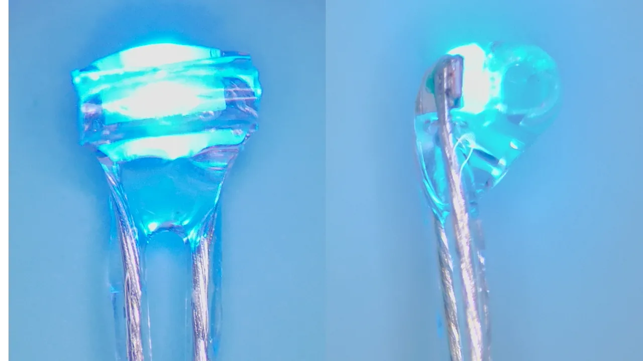
Our optical cuff is a novel technology: an optical interface for peripheral nerves as small as 100 µm in diameter. We also build electrical interfaces for nerves at this scale.